In this post, I’ll talk about taking an old X200 Thinkpad and replacing the proprietary BIOS with coreboot, removing the Intel ME.
Table of contents:
The page for the x200 on libreboot.org recommends that you upgrade the EC firmware and check the the battery isn’t recalled before replacing the original Lenovo BIOS.
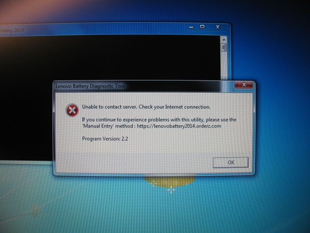
The X200 came with Windows 7. I downloaded LenovoBattery.exe, and ran it:
It needed Internet access, so I verified that this battery was not recalled using the manual method (visiting https://lenovobattery2014.orderz.com/ and entering the serial number there).
To update the EC firmware, I installed latest BIOS from Lenovo for the X200 (6duj48u6.exe).
$ sha256sum Downloads/6duj48u6.exe
9bedafed10c9d1a5294a9334284a5d871744be396c61d1e910c30b3b29a0d6d8  Downloads/6duj48u6.exe
I originally was going to build and flash Libreboot, but I could not get it to build properly from source.
I chose coreboot instead - the coreboot page for the X200 includes a section on disabling the Intel ME.
$ git clone --recurse-submodules https://review.coreboot.org/coreboot.git
Build the toolchain:
$ sudo apt-get install gnat

$ make help_toolchain

$ make crossgcc-i386 CPUS=2
$ make crossgcc-x64 CPUS=2

$ make crosstools-i386 CPUS=2
$ make crosstools-x86 CPUS=2
Here is the configuration I used (only showing deviation from defaults):
Mainboard  --->
    Mainboard vendor (Lenovo)  --->
    Mainboard model (ThinkPad X200 / X200t)  --->
    ROM chip size (8192 KB (8 MB))  --->
    (0x7fd000) Size of CBFS filesystem in ROM

Chipset  --->
    [ ] Beep on fatal error
    [*] Flash LEDs on fatal error

Devices  --->
    Graphics initialization (Use native graphics init)  --->
    Display  --->
        Framebuffer mode (Legacy VGA text mode)  --->

Generic Drivers  --->
    [ ] Support Intel PCI-e WiFi adapters

Console  --->
    [*] Use onboard VGA as primary video device

Payload  --->
    Add a payload (SeaBIOS)  --->
    SeaBIOS version (1.11.0)  --->
After building the coreboot rom, I followed the “old” instructions on how to remove the Intel ME:
jwm@magnus:~/src/libreboot/resources/utilities/ich9deblob [master] [] $ make

jwm@magnus:~/src/libreboot [master] [] $ ./resources/utilities/ich9deblob/ich9gem --macaddress XX:XX:XX:XX:XX:XX

jwm@magnus:~/src/coreboot/x200 [master] [] $ cp ~/src/libreboot/ich9fdgbe_8m.bin .

jwm@magnus:~/src/coreboot [master] [] $ dd if=x200/ich9fdgbe_8m.bin of=build/coreboot.rom bs=1 count=12k conv=notrunc
12288+0 records in
12288+0 records out
12288 bytes (12 kB, 12 KiB) copied, 0.0168296 s, 730 kB/s
coreboot.rom is now ready for flashing.
I used a Raspberry Pi Zero W (with the creative hostname of
liberator) as the SPI programmer.
flashrom supports the RPi out of the box:
pi@liberator:~ $ sudo apt-get install build-essential \
    pciutils usbutils libpci-dev libusb-dev libftdi1 \
    libftdi-dev zlib1g-dev subversion \
    libusb-1.0-0-dev git
pi@liberator:~ $ git clone https://review.coreboot.org/flashrom.git
pi@liberator:~ $ cd flashrom
However, I found that the X200 SPI hack patch on the coreboot Gerrit’s flashrom section was required for flashing the X200. Apply that patch, and then build:
pi@liberator:~/flashrom $ make
Enable the RPi SPI ports either in raspi-config or manually using
modprobe:
pi@liberator:~/flashrom $ sudo raspi-config

pi@liberator:~/flashrom $ sudo modprobe snd_bcm2835
pi@liberator:~/flashrom $ sudo modprobe spidev
Opening up the X200 is straight forward (see the maintenance guide).
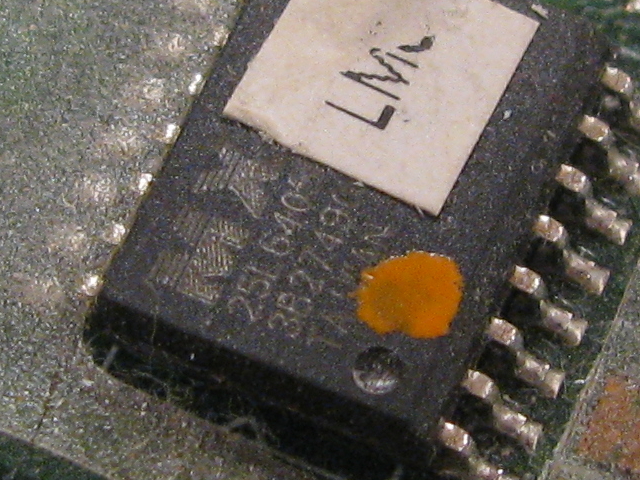
The SPI chip for this X200 is MX25L6405D:
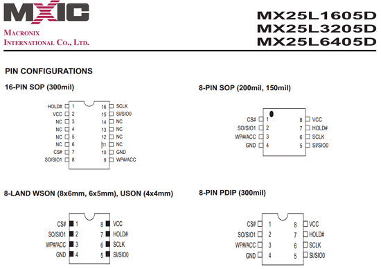
Here is a copy of the pinout of the SPI chip from the Libreboot page for the X200 (hosted here to save their bandwidth):
It requires a SOIC 16 test clip with 1.27 mm pin separation, which I bought from newark.com (specifically I bought the Pomona 5252).
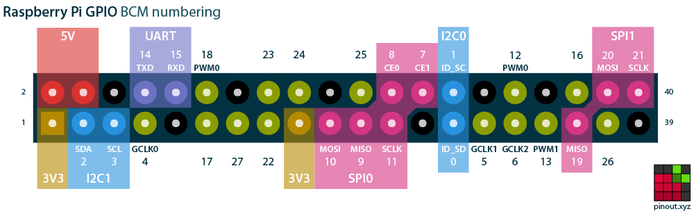
Following pinout.xyz’s RPi pinout and the Libreboot page for using an RPi as a flasher for the X200, I attached the 5252 to the chip:
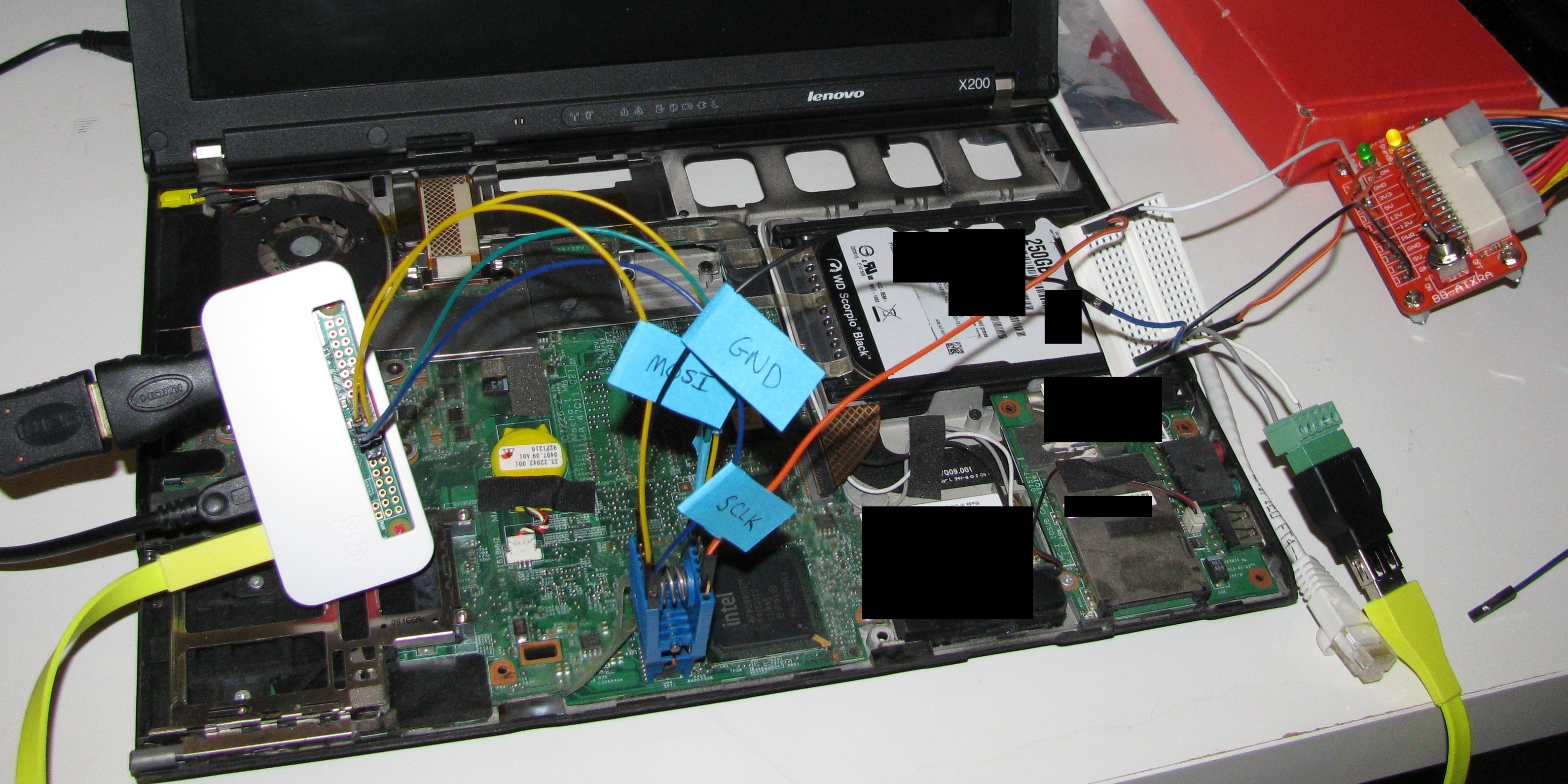
With the X200 SPI HACK patch, and using an ATX power supply breakout to supply 3.3V to the SPI chip and 5V to power the RPi, I was able to read at 10 MHz without problems.
One important note: I connected the RPi’s ground to the SPI chip, and only connected 3.3V from the ATX break out. This was essential for the RPi to recognize that a SPI chip was attached. The image above shows ground from the ATX breakout to the SPI chip, which didn’t work for me. I took the picture before a lengthy session trying to figure out why the chip wasn’t registering. More on this in the next section.
Before anything else, copy the original BIOS at least 3 times to ensure that your 5252 is correctly attached, the power supplied to the setup is adequate, and that there is no interference:
pi@liberator:~/flashrom $ time sudo ./flashrom \
    -p linux_spi:dev=/dev/spidev0.1,spispeed=10000 \
    --chip 'MX25L6405D' \
    -r x200_orig_bios.rom
Verify that the image checksums are the same:
pi@liberator:~/flashrom $ sha256sum x200_orig_bios*
a9a007fe9ea1bb89496a0cc86c07578c245299b6e0e9f7dc74643cf4ffca64fb  x200_orig_bios_2.rom
a9a007fe9ea1bb89496a0cc86c07578c245299b6e0e9f7dc74643cf4ffca64fb  x200_orig_bios_3.rom
a9a007fe9ea1bb89496a0cc86c07578c245299b6e0e9f7dc74643cf4ffca64fb  x200_orig_bios_4.rom
a9a007fe9ea1bb89496a0cc86c07578c245299b6e0e9f7dc74643cf4ffca64fb  x200_orig_bios.rom
Also verify that the images contain data:
pi@liberator:~/flashrom $ xxd x200_orig_bios.rom | tail -n1280 | head -n8
007fb000: 82f9 5682 00fe f1ab b417 cab4 1b81 27b7  ..V...........'.
007fb010: 34be cf16 f6ab 08ae 826e 3b41 b555 a0dc  4........n;A.U..
007fb020: b24e 90d5 da0d aaad 0401 f646 aed0 6d55  .N.........F..mU
007fb030: 6837 2c53 eacd 5da0 daaa d040 1e50 d5da  h7,S..]....@.P..
007fb040: 0daa ad06 e582 6c8d 5da0 daaa d040 1f3c  ......l.]....@.<
007fb050: c5da 0daa ad06 e4f4 fdf3 1768 36aa b410  ...........h6...
007fb060: 07c5 3176 836a ab41 b939 3f54 c5da 0daa  ..1v.j.A.9?T....
007fb070: ad04 01f9 862e d06d 5568 3726 a7bd 3176  .......mUh7&..1v
This is critical - if there was a bridged connection or an improperly connected wire, it is possible that the image could be all 0x00 or 0xFF. The checksums of those images would all match but the contents would be bogus.
Note: I first read at spispeed=100 to copy the original BIOS, and this
required 18 minutes per read. Four reads totalled about an hour and a
half, so allocate your time appropriately.
Be careful when getting your setup to work. There are many ways in which performing In-System Programming (ISP) can go wrong. It’s easy to get into a state where you’re rapidly trying different things to get it to work, and you’ll discover (at least this was my experience) that it will work (or won’t work) and you won’t know why.
For example: there was a strange problem where both reads and writes only seemed to be stable after a write. I would connect the clip, attempt reading multiple times to verify that the setup worked, and each time the checksum would be different. If I wrote a coreboot rom once (note that I had successfully read the original BIOS previous to this, else this would be destructive), read and write operations after that would be stable.
Even now I don’t know how I got into this state.
Cargo cult science is defined as:
practices that have the semblance of being scientific, but do not in fact follow the scientific method.
The better way of thinking and problem solving would include hypothesis, experimentation, observation, and only changing one variable at at time. I didn’t practice this, so there were nights when flashing would oscillate from stable to unstable and back, without me knowing why. I was generally mindful enough to only change one variable at a time, but not perfect.
In searching online for guides detailing how to externally flash coreboot, I saw:
I had to ask in the #flashrom IRC channel for advice, and in there was where I was pointed to the X200 SPI HACK patch, which ultimately was one of the key things that made my setup stable.
Here are the things that worked for me:
spispeed=10000)Transfer over coreboot.rom and write it!
jwm@magnus:~/src/coreboot [master] [] $ scp build/coreboot.rom pi@liberator:flashrom/

pi@liberator:~/flashrom $ time sudo ./flashrom \
    -p linux_spi:dev=/dev/spidev0.0,spispeed=10000 \
    --chip 'MX25L6405D' \
    -w coreboot.rom

flashrom v0.9.9-115-g25fde40 on Linux 4.9.35+ (armv6l)
flashrom is free software, get the source code at https://flashrom.org

Using clock_gettime for delay loops (clk_id: 1, resolution: 1ns).
Found Macronix flash chip "MX25L6405D" (8192 kB, SPI) on linux_spi.
Reading old flash chip contents... done.
Erasing and writing flash chip... Erase/write done.
Verifying flash... VERIFIED.

real    0m24.994s
user    0m0.610s
sys     0m2.050s
I installed 8GB of RAM, and a 1 TB SSD. After the requisite burn-in of both, and several passes of memtest, I installed Debian 9.
The hostname for this machine is sleevedeck, combining sleeve and deck from two favourite novels of mine.